

 English
 français
 русский
 español
يبحث
ما الذي تبحث عنه?
يبحث

Antenna mounting interfaces for radar towers must be designed with a singular focus: maintaining absolute pointing accuracy. This requires a highly rigid, precision-machined mounting flange with a strict flatness tolerance to prevent structural warp from misaligning the radar beam. The interface design must perfectly match the radar manufacturer’s Interface Control Document (ICD), utilizing CNC punching and drilling to achieve sub-millimeter hole alignment. Furthermore, the design must account for welding distortion, hot-dip galvanizing thickness variations, and the integration of azimuth reference marks to facilitate exact on-site calibration.
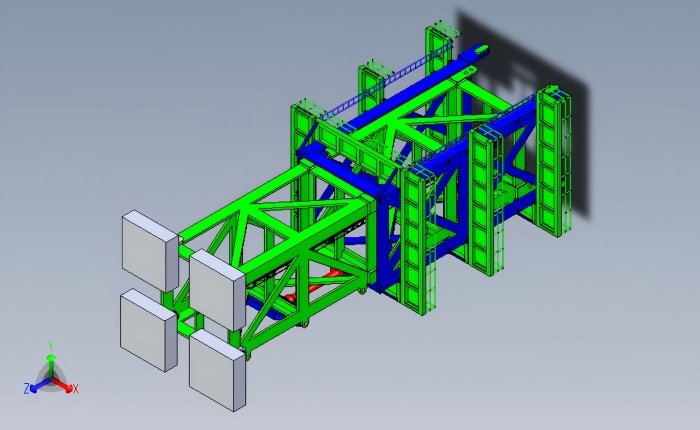
· Flatness Governs Accuracy: The mounting flange must be exceptionally flat. Even a fraction of a degree of tilt across the flange can result in significant pointing errors over long distances.
· OEM Compatibility is Mandatory: The interface must be built exactly to the radar OEM's ICD (Interface Control Document). Bolt hole patterns, clearances, and cable/waveguide apertures must be perfectly replicated.
· Mitigating Fabrication Stresses: Heavy welding at the platform level can warp the flange. Fabricators must use advanced welding sequences, stiffeners, and CNC machining after welding to restore precise tolerances.
· Galvanizing Considerations: The zinc coating applied during hot-dip galvanizing adds thickness. The flange must be designed with machining allowances, or the mating surface must be milled post-galvanizing to ensure a perfectly flat metal-to-metal contact.
· Integration of Reference Points: The steel structure must include precise optical or mechanical reference marks (azimuth and elevation) to allow technicians to align the radar during installation.
The foundation of radar accuracy is the mounting flange—the heavy steel interface where the radar pedestal bolts onto the tower platform.
Design Requirements:
· Thickness and Rigidity: The flange plate must be thick enough (often 25mm to 50mm+ depending on the radar payload) to resist bending moments without flexing. It is typically heavily reinforced with vertical gusset plates underneath.
· Flatness Tolerance: The flange surface must be machined flat within strict tolerances (often measured in millimeters per meter, or fractions of a degree). If the flange is not flat, forcing the radar base to bolt down will induce internal stresses in the radar's mechanical components, leading to premature bearing failure and tracking errors.
· Leveling Mechanisms: While flanges are machined flat, during tower erection, minor deviations occur. The design should incorporate leveling nuts or the ability to use precision shims between the radar base and the flange.
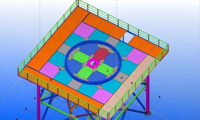
The radar tower interface is not just about load-bearing; it is about seamless integration with sensitive electronics.
· Bolt Patterns: The bolt circle diameter, number of bolts, and thread specifications must exactly match the radar pedestal. High-strength bolts (often Grade 8.8 or 10.9) are used with double nuts or thread-locking compounds to prevent loosening from continuous antenna rotation.
· Cable and Waveguide Access: Radar systems utilize thick, rigid waveguides and heavy power cables. The interface design must include dedicated cable drop holes and waveguide entry ports (often flanged and weather-sealed) positioned exactly where the radar manufacturer requires.
· Clearance for Servicing: The interface must allow technicians to access the mounting bolts and the radar's slip rings without obstruction from the platform's structural beams.
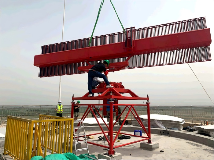
Before the radar can track an aircraft, the tower must tell the radar where "North" is.
· Azimuth Reference Marks: The steel platform must be marked with a permanent, highly visible azimuth reference point (e.g., a machined notch or a specific bolt marked with an arrow). This allows the radar installation crew to align the radar's mechanical zero with true North.
· Elevation Datum: A leveling datum must be machined into the flange so technicians can verify the exact tilt of the radar base using precision spirit levels or laser alignment tools.
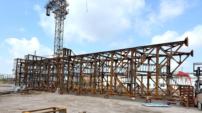
Translating these precise engineering requirements into a massive steel structure requires specialized manufacturing processes.
| Design Parameter | Standard Telecom Interface | Radar Tower Interface |
|---|---|---|
| Flange Flatness | Standard structural tolerance | Precision machined; strict flatness limits |
| Hole Tolerance | ±1.0 mm | ±0.5 mm or tighter (often CNC match-drilled) |
| Alignment | Basic leveling | Optical reference marks for azimuth/elevation |
| Surface Finish | Galvanized surface is acceptable | Machined bare metal or masked post-galvanizing |
| Waveguide/Coax | Simple cutouts for RRUs | Sealed, flanged entry ports for rigid waveguides |
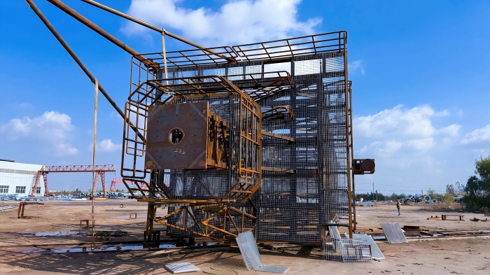
At Altai Tower, we understand that a radar is only as accurate as the steel it sits on. Our engineering and manufacturing processes are specifically tailored to meet the stringent demands of radar integrators.
When fabricating a radar tower platform:
· Advanced Welding Control: Our automated welding processes and internal quality protocols ensure that the heat input is carefully managed. This minimizes the warping of the heavy antenna mounting flange.
· CNC Precision Machining: We use high-capacity CNC drilling equipment to punch bolt holes directly from the client's ICD data. This guarantees that the radar pedestal will mate perfectly without field reaming.
· Surface Protection: We carefully manage the hot-dip galvanizing (ASTM A123) process. For mating surfaces that require absolute flatness, we can apply specific masking protocols or post-galvanizing milling to ensure a perfectly level interface.
Q1: Why can't we just use a standard telecom tower flange for a radar?
A: Standard telecom flanges are designed for static antennas and have looser flatness tolerances. Forcing a precision radar pedestal onto an uneven flange will distort the radar's gearbox and bearings, leading to excessive vibration, wear, and severe pointing errors.
Q2: What is the acceptable flatness tolerance for a radar mounting flange?
A: The exact tolerance depends on the radar manufacturer's specifications. However, it is typically measured in fractions of a millimeter across the entire flange surface. The radar OEM will specify this in their Interface Control Document (ICD), and the steel fabricator must machine the flange to meet it.
Q3: How does hot-dip galvanizing affect the flatness of the mounting flange?
A: Hot-dip galvanizing adds a zinc layer of 85 to 100+ micrometers. Because this layer can be slightly uneven, it disrupts the flat surface. For critical mounting surfaces, fabricators must either mask the surface before dipping or machine the surface flat after galvanizing.
Q4: How are the radar cables and waveguides routed through the interface?
A: The steel platform is typically designed with a central aperture or a series of specific cutouts to allow waveguides and cables to pass from the equipment shelter below up into the radar pedestal. These penetrations must be designed with weatherproofing (e.g., sealed flanges or rubber grommets) to prevent water ingress into the radar unit.
Q5: What information does Altai Tower need from a client to design the interface?
A: We need the radar manufacturer's Interface Control Document (ICD) or outline drawing. This must include the bolt circle diameter, bolt size, hole pattern, total payload weight, center of gravity, and the location of cable/waveguide penetrations.
The antenna mounting interface is the most critical square meter of a radar tower. If the flange is not perfectly flat, the bolt holes misaligned, or the reference marks missing, the most advanced radar system in the world will underperform.
At Altai Tower, we bridge the gap between heavy structural steel fabrication and precision mechanical engineering. By utilizing CNC machining, advanced welding control, and rigorous quality assurance, we deliver mounting interfaces that guarantee your radar system achieves its maximum operational accuracy.
Ready to discuss your radar tower interface requirements? Provide our engineering team with your radar's Interface Control Document (ICD) and payload specifications. We will deliver a detailed design and manufacturing plan that guarantees perfect integration.



 شبكة IPv6 مدعومة