

 English
 français
 русский
 español
يبحث
ما الذي تبحث عنه?
يبحث
Radar equipment weight is not just a number on a specification sheet—it is the primary driver of tower structural design. A typical weather radar antenna assembly weighs 4.5 tonnes (radome, antenna, and pedestal), and a complete CINRAD radar antenna system can reach 14,088 kg—with the antenna pedestal alone weighing 10,000 kg. These concentrated, top-heavy loads generate enormous bending moments at the tower base, dictate foundation dimensions, determine the required structural stiffness, and drive the tower’s natural frequency targets. Unlike telecom towers—where equipment loads are relatively light and distributed—radar towers must be engineered from the ground up to carry heavy, concentrated, often dynamic loads at extreme heights. The weight of the radar equipment is the starting point for every structural calculation.
· Radar equipment is heavy and concentrated: A weather radar antenna assembly can weigh 4.5 tonnes at the roof level, with the pedestal alone accounting for 10,000 kg.
· Weight location matters more than total weight: The same equipment mass placed at 30 meters generates three times the bending moment at the base as equipment placed at 10 meters—this is why height and weight must be designed together.
· Foundations are sized by overturning moment: The 100+ tonne-meter overturning moment from a top-mounted radar antenna drives foundation designs that may require 24 piles of 1.2m diameter and 28.8m length.
· Dynamic loads amplify static weight: The rotating antenna and wind acting on the radome create cyclic loads that must be added to the static equipment weight—under 60 m/s wind, the maximum downforce per leg on a radar interface tower can reach 13,620 kg.
· Natural frequency requirements govern stiffness: To maintain pointing accuracy, the tower's natural frequency must exceed 1 Hz—a requirement that forces a stiffer (and heavier) structure than a telecom tower of equivalent height.
· Platform loads are substantial: Radar platforms must support radome (140 kN), antenna (85 kN), platform equipment (8 kN/m²), and live loads (200 kg/m² minimum).
The first step in any radar tower design is determining what the tower must carry. Radar equipment is significantly heavier than telecom equipment, and the weight is concentrated rather than distributed.
Weather Radar Systems
A typical meteorological radar installation consists of three main components:
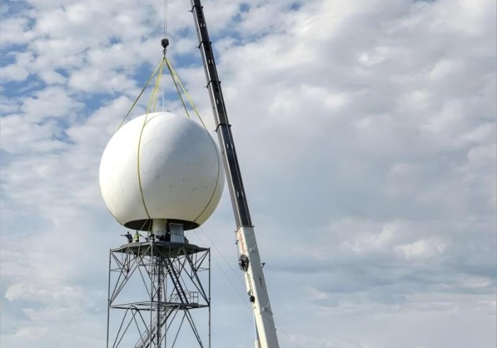
Radome: The protective dome that houses the antenna. A standard 11.8-meter diameter radome weighs approximately 3,500 kg. Larger radomes can weigh 4.2 tonnes or more.
Antenna: The parabolic dish that transmits and receives radar signals. A typical weather radar antenna weighs 1,500–2,100 kg.
Pedestal: The rotating mount that supports the antenna. This is often the heaviest single component—a weather radar pedestal weighs 10,000 kg (10 tonnes), while smaller radar pedestals can weigh 21,500 lbs (9,752 kg).
Combined System Weight
The total weight of a complete weather radar antenna system—radome, antenna, and pedestal—reaches 14,088 kg according to CINRAD specifications. When this system is mounted on an interface tower, the combined static load on the building or foundation below is 24,088 kg (including the 10,000 kg interface tower weight).
For comparison, a typical telecom tower supports 1,000–2,000 kg of distributed antenna equipment—less than one-tenth the weight of a single radar installation.
The total weight of the radar equipment is only part of the story. The location of the center of gravity (CG) determines how that weight translates into structural loads.
Vertical Position of CG
The center of gravity of the radar system is typically located at the antenna pedestal, roughly at the midpoint of the radome. For a CINRAD system with a 10.6-meter radome height, the CG is approximately 5–6 meters above the mounting interface. This means the entire weight of the system acts as a point load at that height, creating a bending moment at the tower base equal to:
Moment = Weight × Height of CG
For a 14,088 kg system with its CG at 5 meters above the tower top, and the tower top at 30 meters, the CG is 35 meters above the base. The moment is:
M = 14,088 kg × 35 m ≈ 493,080 kg·m
This is the moment the tower must resist—and it is enormous.
Horizontal Offset of CG
Accurate determination of the antenna's center of gravity is essential for mechanical analysis and design verification. If the CG is offset from the tower's vertical axis—due to asymmetric antenna mounting or counterweight placement—it creates additional eccentric moments that must be accounted for.
The height at which radar equipment is installed is as important as its weight. The bending moment at the tower base is directly proportional to the height of the equipment—the same mass at twice the height generates twice the moment.
Comparison: 20m vs. 30m Installation
Consider a 14,088 kg radar system installed at two different heights:
| Installation Height | Moment at Base (approx.) |
|---|---|
| 20 meters | 281,760 kg·m |
| 30 meters | 422,640 kg·m |
The difference is 50% more bending moment for a 10-meter increase in height. This is why radar tower heights are carefully optimized—every additional meter of elevation increases the structural demand exponentially.
Height vs. Coverage Trade-off
Radar towers must be tall enough to achieve the line-of-sight coverage required for the radar's mission. A weather radar needs to see over terrain and buildings; an air traffic control radar needs to detect aircraft at low altitudes. But taller towers mean heavier structures and larger foundations. The designer must balance coverage requirements against structural cost.
The weight of the radar equipment is only the static load. In operation, the tower must also resist dynamic loads that can be significantly larger.
Rotating Antenna
Most radar antennas rotate continuously during operation. A weather radar dish typically rotates at 6 revolutions per minute. This rotation creates:
Centrifugal forces: Even with balanced antenna assemblies, slight imbalances create cyclic loads
Gyroscopic effects: The rotating mass resists changes in orientation
Cyclic loading: The tower experiences repeated load cycles that can cause fatigue
Wind Load on the Radome
The radome presents a large surface area to the wind—an 11.8-meter diameter radome has a projected area of approximately 109 m². Under 60 m/s wind (equivalent to a Category 4 hurricane), the CINRAD system generates:
Overturning moment: 101,155 kg·m
Maximum uplift per leg: 12,349 kg
Maximum downforce per leg: 13,620 kg
Maximum shear per leg: 8,989 kg
These dynamic loads must be added to the static equipment weight when designing the tower and foundation.
Ice and Snow Loads
Ice accumulation on the radome adds significant weight. The CINRAD radome is designed to withstand a maximum load of 235 kg/m², with an estimated ice load of approximately 26 tonnes under worst-case conditions. The radome itself is designed to withstand 330 kg/m² of snow and wind speeds up to 240 km/h.
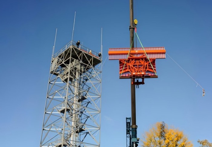
The foundation is the final element in the load path from the radar equipment to the ground. It must resist the combined effects of equipment weight, wind moment, and dynamic loads.
Overturning Moment Governs Design
For a radar tower, the foundation is typically governed by the overturning moment rather than the vertical weight. The foundation must be heavy enough and wide enough to prevent the tower from tipping over under the maximum wind load.
A representative radar tower foundation design for a system with significant equipment weight includes:
Pile foundation: Cast-in-site concrete piles
Designed pile length: 28.8 meters
Number of piles: 24
Pile diameter: 1.2 meters
This foundation is designed to prevent differential settlement that would degrade radar pointing accuracy—the permissible horizontal deflection of the building must be not more than 0.075 degrees.
Foundation for Building-Mounted Radar
When radar equipment is mounted on a building roof, the building structure itself must be designed to carry the concentrated load. A CINRAD radar antenna system mounted on a building rooftop imposes a static load of 24,088 kg on the roof structure. The building's structural system must be designed to distribute this load to the foundation without excessive deflection.
The platform or interface structure between the radar equipment and the tower must be designed to safely transfer all loads.
Interface Tower for CINRAD Systems
The CINRAD radar system uses a dedicated interface tower—a 2.2-meter steel structure with 8 support legs arranged in concentric squares. The outer leg centers are spaced 6,502 mm apart, and the inner legs 1,524 mm apart. This interface tower weighs 10,000 kg and is bolted to the building rooftop.
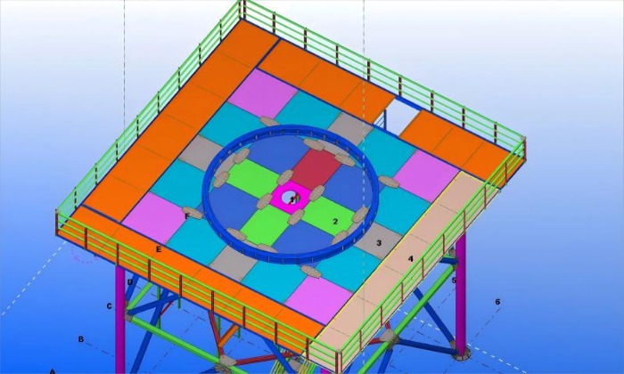
Platform Design Requirements
Radar platforms must be designed for both equipment and personnel loads:
| Load Type | Typical Value |
|---|---|
| Radome | 140 kN |
| Antenna | 85 kN |
| Platform equipment | 8 kN/m² |
| Live load (personnel) | 200 kg/m² minimum |
These platforms must also function as stiffening diaphragms—their floor beams and bracing contribute to the tower’s overall rigidity, helping to achieve the natural frequency requirements.
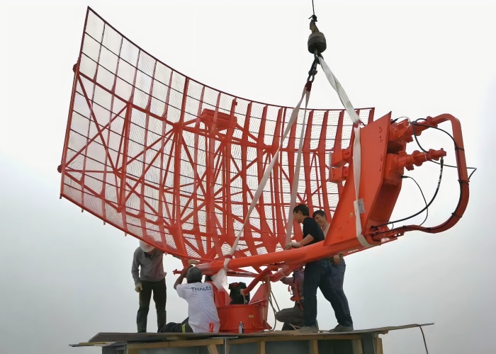
Qingdao Altai Tower Co., Ltd. is a professional manufacturer of telecommunication towers, power towers, and tower accessories, established in 2003. The company specializes in the design, manufacturing, and installation of steel towers, with products exported to more than 100 countries and regions. Its radar support tower product line demonstrates how equipment weight drives tower design.

Qingdao Altai Tower supplied a 30-meter radar support tower for pest migration monitoring in China, completed in March 2026. This project demonstrates the application of radar tower design principles to a non-traditional monitoring application—tracking insect migration to support agricultural health.
Design considerations driven by equipment weight:
Structural sizing for concentrated load: The tower was designed to support the radar antenna and monitoring equipment at the top, with structural members sized to resist the resulting bending moment.
Foundation design for overturning resistance: The foundation was engineered to resist the overturning moment generated by the top-mounted equipment under design wind loads.
High-stiffness lattice configuration: A lattice structure was selected to achieve the required natural frequency while minimizing material weight—a balance made possible by the tower's multi-leg configuration.
Integrated platform design: The platform was designed to support both the radar antenna and monitoring equipment, with load distribution provisions to avoid point loading on individual members.
Hot-dip galvanized construction per ASTM A123 for long-term corrosion protection.
For radar tower projects, Qingdao Altai Tower integrates equipment load analysis, foundation engineering, and structural design from the outset—ensuring that the tower's capacity meets the demands of the specific radar system it will support.
Radar equipment weight is not a single parameter—it is a cascade of design drivers that flows from the specification sheet to the foundation. The weight of the radome, antenna, and pedestal determines the static load. The location of the center of gravity determines the bending moment. The installation height amplifies that moment. The rotating antenna and wind on the radome add dynamic loads that can exceed the static weight. And the foundation must be sized to resist it all.
For radar tower projects, the engineering process begins with a simple question: What equipment will the tower carry, where is its center of gravity, and at what height will it be installed? The answers to these three questions determine everything that follows—the structural configuration, member sizes, connection details, foundation dimensions, and ultimately the tower’s cost and performance.
Understanding these relationships is essential for project engineers, procurement managers, and anyone involved in specifying or evaluating radar support structures. The weight of radar equipment is not just a number—it is the starting point for every structural calculation that follows.
Ready to specify a radar support tower that meets your equipment’s load requirements? Contact Qingdao Altai Tower’s engineering team today for custom design, load analysis, and a detailed proposal.



 شبكة IPv6 مدعومة