

 English
 français
 русский
 español
يبحث
ما الذي تبحث عنه?
يبحث

A radar tower is designed for wind load through a rigorous, physics-based process that treats the structure as a precision instrument under lateral assault. The design begins by calculating the Effective Projected Area (EPA) of everything the wind “sees”—the open lattice frame, the radar pedestal, and most critically, the large radome, which acts as a sail. This area is multiplied by the site-specific design wind pressure (often specified as a 3-second gust of 250 km/h or higher for critical installations) to determine the total overturning force. Because even a fraction of a degree of deflection can corrupt radar data, the tower is then engineered for exceptional stiffness, with strict deflection limits (e.g., 0.1° at design wind speed) and a natural frequency tuned to avoid resonance with wind or the rotating antenna.
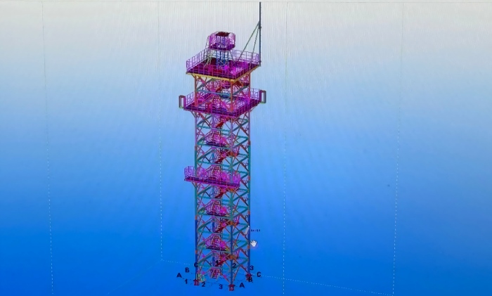
· The Radome is the Dominant Wind Sail: The large protective dome (often 8–15 m in diameter) presents a massive, solid surface to the wind. Its projected area—not the slender lattice frame—dictates the majority of the wind load.
· Height Multiplies the Moment: Wind pressure increases with height, but the bending moment at the tower base grows with the square of the height. A taller tower to clear obstacles or extend range therefore faces disproportionately larger structural demands.
· Deflection is the Design Driver, Not Just Stress: Unlike telecom towers, a radar tower’s primary wind-related failure mode is functional, not structural. A deflection of 0.1° to 1.0° under design wind can render the radar useless, making stiffness the governing criterion.
· Open Lattice Geometry Cuts Drag: An open lattice tower allows wind to pass through, reducing wind drag by 60% compared to a solid monopole of equivalent height—a critical advantage for a structure dominated by a top-mounted radome.
· Site-Specific Wind Speed Governs Everything: Design standards like TIA-222-H require the use of localized basic wind speeds (county-by-county in the U.S.), ensuring the tower is engineered for the actual wind climate at its specific location, not a generic regional average.
Who is searching for this information?
| User Type | Primary Intent | Key Concerns |
|---|---|---|
| Structural Engineers | Understand the calculation methodology for radar tower wind loads | EPA calculation, pressure coefficients, deflection limits, standards (TIA-222) |
| Radar System Engineers | Specify structural performance requirements for a new installation | How much movement degrades data, what natural frequency is required |
| Procurement Managers | Evaluate vendor proposals and cost drivers | Why radar towers are more expensive, what “design wind speed” means |
| Site Planners | Assess feasibility for a specific location with known wind hazards | Local wind speeds, terrain exposure, foundation implications |
Search intent summary: Users want to understand the specific factors that make radar tower wind design different from standard tower engineering. The core question is: "What exactly must be calculated, and to what tolerance, to ensure the radar works in the wind?"
1. How does the radome's size affect the wind load? Does a larger dome require a fundamentally stronger tower?
2. How is the Effective Projected Area (EPA) of the radome calculated? Is it simply the frontal area?
3. How does tower height change the wind load calculation? Is the relationship linear or exponential?
4. What is the maximum allowable deflection for a radar tower? How is it measured (degrees, millimeters, or H/x)?
5. What design wind speed should be used? Is it a 3-second gust or a sustained wind?
6. How does TIA-222 handle the "sail effect" of a radome? Are there specific coefficients for domes?
7. Can wind tunnel testing or CFD replace code-based calculations? When is it required?
8. How does the open lattice design of the tower itself affect wind load?
Section 1: The Three Inputs of Wind Load Design
Equipment area, tower height, and design wind speed.
Section 2: Equipment Area — The Radome as a Sail
Projected area calculation, drag coefficients, and appurtenance treatment per TIA-222-H.
Section 3: Tower Height — The Moment Amplifier
How height multiplies wind force into overturning moment at the base.
Section 4: Design Wind Speed — Site-Specific and Statistical
TIA-222-H methodology, risk categories, and survival wind speed specifications.
Section 5: From Moment to Structure — Member Sizing and Foundation Design
How the calculated moment drives structural and foundation requirements.
Section 6: Deflection Limits — The Functional Requirement
Why pointing accuracy dictates stiffness beyond strength.
Section 7: Case Study — Altai Tower Wind-Resistant Radar Solutions
Engineering parameters and manufacturing capabilities.
Section 8: FAQ
Common questions and answers.
Wind load design for any structure begins with a simple physical relationship: the force exerted by wind is the product of dynamic pressure and the area resisting that pressure. For a radar tower, the calculation is more complex than for a simple building because the structure is slender, the equipment is concentrated at height, and the equipment itself presents a large, often rounded surface to the wind.
Three inputs govern the entire calculation:
Equipment Area: The projected area of the radome, antenna, and all other appurtenances exposed to wind.
Tower Height: The elevation at which that area is presented to the wind—and the lever arm through which the resulting force acts on the foundation.
Design Wind Speed: The site-specific wind speed that the structure must resist, expressed as a statistical return-period value.
Each input is developed separately, then combined to determine the design wind force and overturning moment.
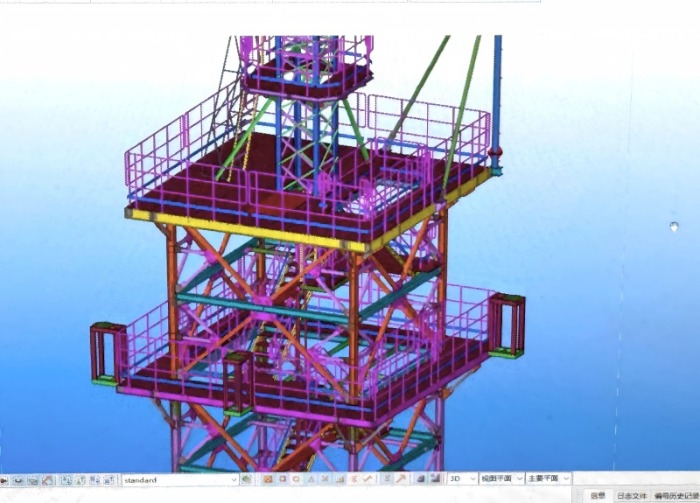
The most distinctive feature of a radar tower's wind profile is the radome. A typical weather radar radome is a sphere or truncated sphere approximately 11.8 meters in diameter. Its projected area—the silhouette presented to the wind—is approximately:
A_projected = π × (D/2)² ≈ 3.14 × (5.9)² ≈ 109 m²
For a larger radome of 4.2 tonnes or more, the projected area can exceed 130 m². This is a substantial solid surface—comparable to the side of a small building—but elevated on a slender tower and carrying sensitive equipment.
How TIA-222-H treats appurtenances:
The standard's design wind load criteria are based on determining the design wind forces on the bare structure first, then adding the design wind forces from appurtenances and supporting guys. The determination of the effective projected area of a structure with appurtenances—feed lines, antennas, mounting frames, platforms, climbing facilities—was considered by practicing engineers as the most significant determination impacting the design and analysis of the structures covered by the standard.
The standard requires consideration of shielding and wake interference effects. For wind approaching from one direction, an appurtenance on the windward side may shield the structure behind it; for wind from the opposite direction, the structure may shield the appurtenance. TIA-222-H provides reduction factors to account for these effects, though the committee adopted a simplified approach for consistency.
For latticed structures with triangular cross sections, wind directions normal to each face, parallel to each face, and into each apex must be considered—a total of 12 directions for triangular towers, and 8 directions for square cross sections.
Drag coefficients for rounded bodies:
The radome is not a flat plate; its curved surface reduces the effective drag compared to a flat area of the same projected size. Wind tunnel tests and numerical simulations are used to determine pressure distributions and aerodynamic coefficients for specific radome geometries. The local terrain, surrounding buildings, and wind velocity profile all influence the actual pressure distribution on the radome surface.
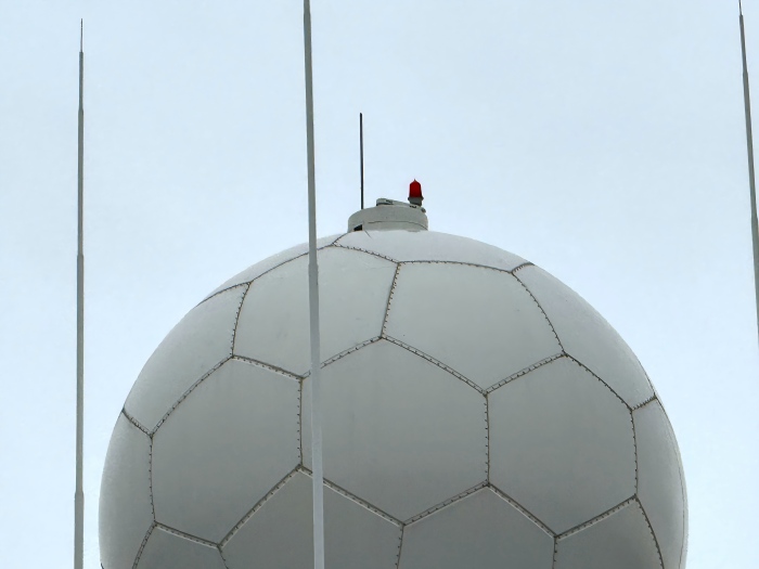
Once the wind force acting on the radome is calculated, the overturning moment at the tower base is determined by multiplying that force by the height at which it acts:
Moment = Force × Height
This relationship is the reason tower height is such a critical design parameter. The same equipment mass—or the same wind-catching area—generates proportionally greater structural demand as it is elevated higher. A 14,088 kg radar system at 30 meters generates three times the bending moment at the base as the same system at 10 meters.
For a CINRAD weather radar system under 60 m/s wind (equivalent to a Category 4 hurricane), the calculated overturning moment reaches 101,155 kg·m. This moment must be resisted by the tower's structural members and, ultimately, by the foundation.
The height effect also compounds with the tower's own wind profile. The tower shaft itself—whether lattice or monopole—presents area to the wind along its entire length. Taller towers have more shaft area, but the dominant contribution for radar towers is almost always the radome and antenna assembly at the top.
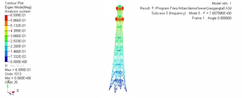
The design wind speed is not a single universal value. It depends on:
· Geographic location: Basic wind speed maps define the statistical wind climate.
· Risk category: Critical infrastructure (such as air traffic control radar) may be assigned a higher risk category, requiring design for a longer return period.
· Exposure category: Open terrain, suburban, or urban—each modifies the wind speed profile with height.
· Topographic effects: Ridges, hills, and escarpments can accelerate wind locally.
TIA-222-H methodology:
The standard adopted the peak wind speed design method: a 3-second average of the recorded peak wind velocities, consistent with the International Building Code (IBC) and the preferred method for accurately calculating wind velocity. The equivalent ultimate 3-second gust wind speeds are obtained by multiplying the 50-year return period 3-second gust wind speeds by 1.18.
Survival vs. operational wind speeds:
Radar towers are often specified with two wind criteria:
· Operational wind speed: The maximum wind speed at which the radar must continue to function within its pointing accuracy specifications. This is typically lower than the survival speed.
· Survival wind speed: The maximum wind speed the tower must withstand without structural damage, even if the radar is temporarily shut down.
Altai Tower's radar support structures are custom-engineered to withstand wind speeds up to 200 km/h and higher, with survival ratings that can be specified for specific site conditions. Some radar tower specifications require survival at 250 km/h.
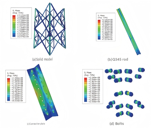
The calculated overturning moment is the primary input for structural and foundation design.
Structural members are sized to resist the combined axial forces, shear, and bending generated by the wind moment. For a lattice tower, the legs on the windward side experience tension (uplift), while the leeward legs experience compression (downforce). Under 60 m/s wind, the CINRAD system generates a maximum downforce per leg of 13,620 kg and a maximum uplift per leg of 12,349 kg. The bracing members transfer shear between the legs and prevent buckling of the compression legs.
Foundations are sized primarily by the overturning moment, not the vertical weight. A foundation that is adequate for the static equipment weight may be entirely inadequate for the wind-induced moment. The CINRAD system's 101,155 kg·m overturning moment drives a foundation design that may require 24 piles of 1.2 meter diameter and 28.8 meter length. The foundation must also satisfy stability checks: a minimum factor of safety against overturning of 2.0 under normal loads and 1.5 under worst-case loads.
A radar tower can be structurally sound—no member yielding, no foundation failure—and still be functionally inadequate if wind-induced deflection exceeds the radar's pointing tolerance. This is the key distinction between radar tower design and conventional structural design.
Typical deflection limits for radar towers are stringent:
Maximum inclination: 0.1 degrees
Maximum torsion: 0.01 degrees
Some specifications require even tighter limits: maximum torque at 0.01° and maximum bending of ±0.1°
These limits are not arbitrary. A deflection of 0.1 degrees at the top of a 30-meter tower translates to a lateral movement of approximately 52 millimeters. For a radar beam that must maintain coherence over tens of kilometers, even this small movement can introduce unacceptable pointing errors and phase distortions.
To meet these limits, the tower must be designed with sufficient stiffness—which, as discussed in the companion blog on vibration, means achieving a high natural frequency and minimizing flexibility. The structural design must therefore balance strength (resisting the wind force without yielding) with stiffness (resisting the wind force without excessive movement).
| Design Consideration | Telecom Tower | Radar Support Tower |
|---|---|---|
| Dominant wind area | Distributed antennas (small individual areas) | Concentrated radome (100+ m²) |
| Primary structural concern | Preventing collapse and excessive sway | Preventing functional degradation from deflection |
| Deflection limit | A few degrees (serviceability) | 0.1° inclination, 0.01° torsion |
| Design wind speed | Site-specific per TIA-222 | Site-specific per TIA-222, often higher risk category |
| Foundation driver | Overturning moment + vertical load | Overturning moment dominated by radome area |
| Stiffness requirement | Moderate | High (natural frequency ≥ 1 Hz) |
Qingdao Altai Tower Co., Ltd. is a professional manufacturer of telecommunication towers, power towers, and specialized radar support structures, established in 2003. The company's radar tower product line is engineered to meet the demanding wind load requirements of weather monitoring, air traffic control, and defense applications.
Wind load design capabilities:
Manufacturing parameters:
| Capability | Specification |
|---|---|
| Production capacity | 3,000 metric tons per month |
| Galvanizing | In-house workshop, ASTM A123 |
| Design standards | ANSI/TIA-222-H, GB 50135 |
| Lead time | 30 days after payment |
Application example: For a coastal radar installation, Altai Tower designed a lattice tower with a custom radome mounting platform. The design accounted for the radome's projected area under the site's design wind speed, calculated the overturning moment at the base, and sized the foundation and leg members accordingly. The tower was hot-dip galvanized for corrosion protection in the salt-laden coastal atmosphere, ensuring that the wind-resistant structure would also resist the corrosive environment over its 50+ year service life.
A: An 11.8-meter diameter radome presents approximately 109 m² of projected area to the wind. Larger radomes can exceed 130 m². This is the dominant wind-catching surface on a radar tower.
A: Design wind speed depends on the site's geographic location, risk category, and exposure. TIA-222-H uses ultimate 3-second gust wind speeds based on statistical return periods. Radar towers are often specified for survival wind speeds of 200 km/h or higher, with some critical installations requiring 250 km/h.
A: The overturning moment at the base is the product of wind force and height. The same equipment area at 30 meters generates three times the bending moment as at 10 meters. Height amplifies wind load linearly for the equipment and contributes additional shaft area as well.
A: Operational wind speed is the maximum at which the radar must continue functioning within its pointing accuracy specifications. Survival wind speed is the maximum the tower must withstand without structural damage, even if the radar is shut down. Both criteria must be verified.
A: The overturning moment is the sum of wind forces on each component multiplied by the height at which each force acts: Moment = Σ(Force × Height). For a concentrated radome load, this simplifies to the total wind force on the radome times its elevation above the base. Under 60 m/s wind, a CINRAD system generates approximately 101,155 kg·m of overturning moment.
A: A tower can be strong enough to avoid collapse but still deflect enough to ruin radar performance. Radar pointing tolerances are typically 0.1° inclination and 0.01° torsion. Exceeding these limits causes pointing errors and data degradation, even if the steel is not overstressed.
A: TIA-222-H requires determining the design wind forces on the bare structure first, then adding the forces from appurtenances (radomes, antennas, platforms, feed lines) with reduction factors for shielding and wake interference. The effective projected area of all components must be considered.
A: Yes. Altai Tower's radar support structures are custom-engineered to withstand wind speeds up to 200 km/h and higher, which covers the range of most hurricane and typhoon events. Survival ratings for extreme sites can be specified even higher.
Wind load design for a radar tower is not a single calculation—it is an integrated engineering process that begins with the projected area of the radome and antenna, applies the site-specific design wind speed per TIA-222-H, determines the overturning moment at the base using the tower height, and then sizes the structural members and foundation to resist that moment without exceeding strict deflection limits. Every input matters: a larger radome catches more wind, a taller tower amplifies the moment, and a higher design wind speed increases the force—each compounding the structural demand.
For radar tower projects, the wind load specification cannot be treated as a generic parameter. It must be developed from the actual equipment geometry, the actual site wind climate, and the actual pointing tolerance of the radar system. Manufacturers like Altai Tower that combine precision fabrication with rigorous wind engineering provide the assurance that the tower will not only stand through the storm but continue to deliver the data fidelity that its mission demands.
Ready to specify a radar tower with verified wind load capacity? Contact Altai Tower's engineering team today for site-specific wind analysis, structural design, and a detailed proposal.



 شبكة IPv6 مدعومة