

 English
 français
 русский
 español
يبحث
ما الذي تبحث عنه?
يبحث
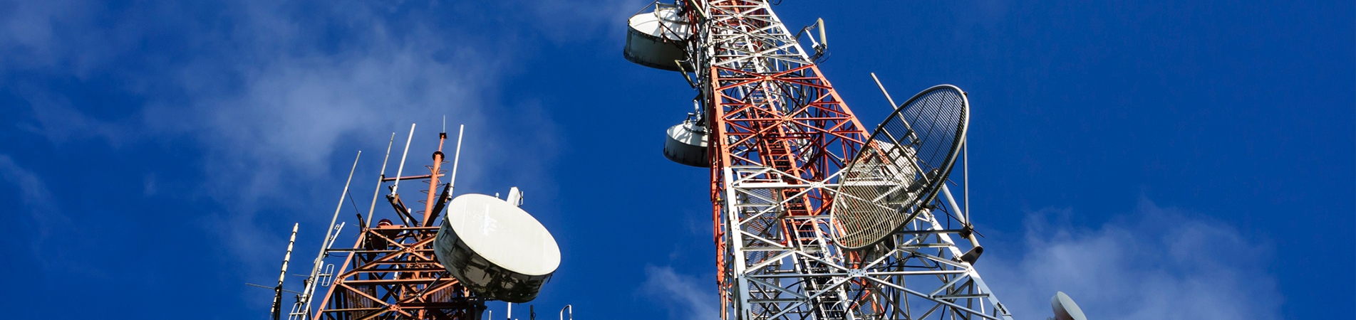
في عالم البنية التحتية الحيوية، قلّما توجد هياكل تتحمل مسؤولية دقيقة مثل مسؤولية... برج دعم الرادار على عكس برج الاتصالات، الذي يُعدّ نطاق تغطية الإشارة معياره الأساسي، فإنّ معيار الأداء النهائي لبرج الرادار هو دقة البيانات. فوضوح صورة الطقس، ودقة مسح مراقبة الحركة الجوية، أو وضوح صورة المراقبة الدفاعية، كلها أمور قد تتأثر سلبًا بأي اهتزاز طفيف في الهيكل الفولاذي الذي يحمل الهوائي. لهذا السبب، تحوّلت فلسفة تصميم أبراج الرادار الشبكية بشكل جذري من مجرد التركيز على المتانة إلى التركيز على الصلابة القصوى، مع التركيز التام على تحقيق تردد طبيعي عالٍ. هذا المعيار ليس مجرد بند آخر في قائمة المواصفات، بل هو بمثابة الحاجز الأساسي الذي يمنع ديناميكيات الهيكل من التأثير سلبًا على الأداء الكهرومغناطيسي.

تستكشف هذه المدونة العلاقة الحاسمة بين ديناميكيات البرج ووظيفة الرادار، وتوضح لماذا يعتبر التردد الطبيعي العالي المعيار الذي لا غنى عنه لسلامة برج الرادار.
يعمل نظام الرادار عن طريق بث موجات راديوية مضبوطة التوقيت بدقة وتحليل الصدى العائد. يجب أن يكون اتجاه توجيه الهوائي معروفًا وثابتًا بدقة تصل إلى أجزاء من الدرجة لتحديد موقع الأهداف بدقة. أي حركة لمنصة الهوائي - بما في ذلك الاهتزازات الطفيفة للبرج نفسه - تُسبب أخطاء في الطور وعدم دقة في التوجيه.
يُعدّ الرنين أخطر أشكال هذه الحركة. فلكل بنية ترددات طبيعية كامنة تهتز عندها بشكل تفضيلي، تمامًا كالشوكة الرنانة. إذا تزامن تردد عامل مُؤثِّر (مثل دوامات الرياح، أو عدم التوازن الميكانيكي الناتج عن دوران الهوائي، أو النشاط الزلزالي الدقيق) مع التردد الطبيعي للبرج، تتراكم الطاقة، مما يؤدي إلى تضخيم الاهتزازات. بالنسبة لبرج الرادار، تكون العوامل المُؤثِّرة حاضرة باستمرار. ويُعدّ كلٌّ من تردد دوران الهوائي (الذي يتراوح غالبًا بين 0.1 و0.5 هرتز في رادارات الطقس) وتردد دوامات الرياح المتدفقة حول البرج من العوامل المُثيرة للقلق بشكل خاص.
إذا كان التردد الطبيعي الأول (الأساسي) للبرج منخفضًا جدًا، فإنه يُخاطر بالتوافق مع ترددات التشغيل أو الترددات البيئية المؤثرة. قد يتسبب هذا الاقتران الرنيني في اهتزاز الهوائي بشكل بطيء ومستمر، مما يُشوه صورة الرادار ويجعل البيانات غير موثوقة أو عديمة الفائدة. الحل هو تصميم التردد الطبيعي الأول للبرج. يكون التردد أعلى بكثير من ترددات القوة المهيمنة مما يخلق "هامش فصل" واسع يمنع اقتران الطاقة.

التردد الطبيعي ( fn إن صلابة الهيكل ليست دالة لقوته، بل لصلابته. ك ) والكتلة ( م تخضع هذه العلاقة للعلاقة الأساسية التالية:

تكشف هذه المعادلة عن متطلبات التصميم
لزيادة التردد الطبيعي، يجب عليك إما زيادة الصلابة ( ك ) أو تقليل الكتلة ( م ).
بالنسبة لهوائيات الرادار الثقيلة وأغطية الرادار، غالباً ما يكون تقليل الكتلة أمراً غير عملي. لذلك، فإن العامل الأساسي هو زيادة الصلابة الهيكلية إلى أقصى حد.
هذا هو أصل "معيار الصلابة". يُصمم برج الرادار ليس فقط لتحمل الوزن، بل لمقاومة التشوه تحت الأحمال الديناميكية بصلابة استثنائية. ويصبح تردده الطبيعي مؤشر الأداء الرئيسي لتلك الصلابة.
يتطلب تحقيق مواصفات تردد طبيعي عالية اتباع نهج تصميم شامل يركز على الصلابة على كل مستوى:
1. اختيار المواد والقطاعات: أساس الصلابة
· الفولاذ عالي القوة: يُتيح استخدام الفولاذ ذي مقاومة الخضوع الأعلى (مثل Q345B/Q355 أو ASTM A572 Gr. 50 بدلاً من Q235) استخدام مقاطع عرضية أكثر كفاءة وصغرًا. ورغم أن القوة هي الميزة، إلا أن زيادة عزم القصور الذاتي الناتجة ( أنا ) من أقسام الأعضاء يعزز بشكل مباشر الصلابة الكلية.
• تحديد حجم الأعضاء الأمثل: يتم تحديد أبعاد الأرجل وعناصر التقوية الرئيسية للتحكم في الانحراف، وليس فقط الإجهاد. وهذا غالباً ما ينتج عنه زوايا أو أنابيب أكثر متانة من تصميم برج الاتصالات الذي يفي بالحد الأدنى من متطلبات الكود.

2. تحسين الشكل الهيكلي: الهندسة هي المصير
زيادة عرض القاعدة: إن الطريقة الأكثر فعالية لزيادة الصلابة الكلية والتردد الطبيعي هي توسيع قاعدة البرج. يؤدي ذلك إلى زيادة كبيرة في ذراع العزم لمقاومة الانقلاب، مما يقلل من الانحراف الجانبي تحت الحمل.
3. صلابة الاتصال: الأضعف
· وصلات صلبة ومقاومة للعزوم: تُصمَّم الوصلات الحرجة، لا سيما عند واجهة منصة الهوائي وعُقد الأرجل الرئيسية، بألواح تقوية لمنع المرونة الموضعية. والهدف هو الاقتراب من ظروف "الطرف الثابت" بدلاً من افتراضات "الطرف المفصلي" كلما أمكن ذلك.
• التثبيت المسبق الشد: يتم تركيب مسامير عالية القوة مع شد مسبق معاير لضمان وصلات احتكاكية تقلل من الانزلاق والحركة، والتي تعد مصادر للصلابة والتخميد غير الخطيين.
بالنسبة لمشروع برج الرادار، فإن التردد الطبيعي ليس فحصًا بعد الحساب؛ بل هو متطلب تصميم إلزامي.
· المواصفات المستهدفة: عادةً ما يحدد مصنعو أجهزة الرادار أو المستخدمون النهائيون الحد الأدنى للتردد الطبيعي الأول (على سبيل المثال، 1.0 هرتز، 1.5 هرتز، أو أعلى)، وغالبًا ما يكون ذلك مع اشتراط أن يظل أعلى من تردد دوران الهوائي وتوافقياته بهامش مريح (على سبيل المثال، هامش فصل بنسبة 150٪).

· التحليل الديناميكي المتقدم: يستخدم المهندسون برامج تحليل العناصر المحدودة (FEA) لإنشاء نموذج نمطي مفصل للبرج، بما في ذلك كتلة وصلابة الهوائي والغطاء الواقي. ويتنبأ هذا التحليل بأشكال وترددات أنماط الاهتزاز للهيكل.
· تكرار التصميم: يتم تحسين التصميم الأولي بشكل متكرر - زيادة أحجام العناصر، وتعديل الدعامات، وتوسيع القاعدة - حتى تفي نتائج تحليل العناصر المحدودة أو تتجاوز هدف التردد المحدد.
· تصديق: بالنسبة للتطبيقات الأكثر أهمية، يمكن التحقق من صحة التصميم من خلال اختبارات نفق الرياح أو التحليل التفصيلي لتفاعل التربة مع الهيكل.
في أبراج الاتصالات، غالبًا ما يهيمن عاملا السعة والارتفاع على النقاش. أما في أبراج الرادار الشبكية، فيبدأ النقاش وينتهي بالصلابة، التي تُقاس بالتردد الطبيعي. هذه المواصفة هي الترجمة الهندسية المباشرة لمتطلبات "انعدام التداخل" من الهيكل الداعم. وهي معيار يُلزم التصاميم بأن تكون أكثر متانة وصلابة ومقاومة للقوى الديناميكية التي تسعى إلى إحداث الاهتزاز.
يُعدّ الاستثمار في تصميم يلبي مواصفات التردد الطبيعي العالي استثمارًا في سلامة بيانات الرادار نفسها. فهو يضمن أن يعمل البرج كأساس صامت وثابت للاستشعار الدقيق، وهو معيار حقيقي للأداء في دمج الهندسة الإنشائية وهندسة الأنظمة.
تعرف على المزيد في www.alttower.com


 شبكة IPv6 مدعومة